The History of 3D Scan Based Reverse Engineering – Why All the Focus on NURBS?
By Tom Charron
By some estimates, more than 80% of parts being produced today do not have 3D definition. Or at least the 3D models aren’t in the hands of the people who need the data. A lot of things may not need a complete 3D CAD model, but if you’ve ever wanted to make a design modification to an existing part, you know the value of being able to open it up in your favorite CAD software, make a few tweaks, and call it a day. That’s where reverse engineering via 3D scanning comes in.
For those of you who have gotten a part scanned, chances are you ended up with a mesh file (STL) or NURBS surface model (IGES). Perhaps you opened the file in your CAD software, and found that it was an uneditable, static model without discreet features. Obviously, a set of surfaces isn’t as useful as a parametric solid that’s driven by a feature tree. But why settle? Why is it that so many reverse engineered parts end up being “dumb” geometry? Let’s take a look at how we got here.
3D scanners have been around for a relatively long time – early commercial systems became available in the mid-90’s. These systems would create dense point clouds of millions of points, which presented a real problem to CAD software (and still do). Using the point clouds themselves in CAD (or CAM or CAE, etc.) was a non-starter. So specialized software (most notably Imageware) was developed to convert point clouds into something useful in CAD. In these early days of scanning, the equipment was far more expensive and hard to use than it is today, and not as accurate as CMMs for catching prismatic shapes, so you’d really only use it to measure things that you had no other way of measuring – complex contours and freeform shapes. It was natural, then, that tools like Imageware would focus on converting the complex shapes into NURBS surfaces, which are great at representing non-uniform geometry.
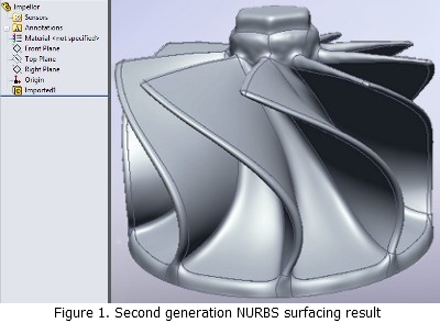
Converting scans to NURBS was a very difficult and time-consuming process with these first generation tools. In the late 90’s a second generation of software came along to address this issue. These tools (lead by Paraform, later Geomagic, and later still, Rapidform) automated this NURBS surface fitting process (but required a perfected mesh). So the focus went on cleaning up and merging all your scans into a single mesh, editing it to remove all holes, noise and flaws, then letting the software automatically or semi-automatically lay down a patch network and fit NURBS surfaces to the mesh. Over the years, we got pretty good at it. Sure, some scans can’t be surfaced because they are too noisy or have too much missing data, but for the right type of scan and the right downstream need, automatic surfacing has gotten pretty good. But there are still two glaring deficiencies to NURBS models from scan data:
- They’re almost impossible to edit in CAD. Changing things like fillets, hole size/position, or anything else ranges from difficult to impossible.
- They’re verbatim copies of whatever you’ve scanned. Real world parts are imperfect, and scanners can introduce error. So what you capture isn’t necessarily what you want your design model to be. Sometimes you want a plane to be a plane, or a patterned feature to be regular.
If you think about it, the second generation scan-to-mesh-to-surfaces process isn’t really reverse engineering at all. It’s just shape capture and conversion. That’s what you want if your goal is a faithful digital reproduction (e.g., into CAE, animation, etc.) or a verbatim physical reproduction (e.g., via CAM or rapid prototyping, etc.). But real reverse engineering entails capturing both form and function for an existing part or assembly.

For years, if you needed to really reverse engineer something, you would scan the part, you’d go through all the work of making the clean mesh and/or NURBS model, and then you’d open it in CAD and manually rebuild a new part model over top of the scanned geometry. This technique yields a parametric CAD model, and lets you make design decisions along the way so the part actually functions as originally intended. But it’s a slow, inefficient process. Not only did you still have to do all the work in the specialized scan processing software to make the mesh and surface models, but then you had to wrestle with CAD software that wasn’t meant to design from imperfect real-world geometry.
At Rapidform, we had customers banging their heads against a wall because of this problem, and we decided to do something about it. So we bit the bullet and completely rewrote our software, embedding the Parasolid kernel and creating a hybrid reverse engineering/CAD application to create Rapidform XOR. With the benefit of hindsight, it’s obvious that if you want to build a CAD model from 3D scan data, the right way is to use CAD commands to do it. All the scanning software vendors kept chasing the NURBS surfacing dream, but nobody stopped to think that the vast majority of parts are designed using solid modeling techniques now, so why shouldn’t we reverse engineer the same way?
Don’t get me wrong; NURBS surface fitting is a useful technique for some parts, and many objects call for a combination of fitted surfaces and prismatic features. But so much of what needs to be reverse engineered is better represented by feature-based modeling. Many people wonder why, in 2010, there’s still so much focus on creating “dumb” NURBS models from scan data, when feature-based solid modeling won the CAD wars in the 80’s and 90’s. But now that you know the history, it makes a lot more sense, doesn’t it?
Tom Charron is the COO of Rapidform Inc., the U.S. arm of INUS Technology, makers of Rapidform 3D scanning software. He’s been involved with 3D scanning for 8 years and remembers the days when who could surface best was all that mattered.
===============
If you wish to write about a CAD software product that you use or develop please click the Contribute to Deelip.com link to know how that can be made possible.